Stay Tuned for optimizations that have been successfully implemented into production.
In the meantime, here are a few links to some published works.
-
Oil Rig Jacking Gear Analysis
The gear mesh stress analysis correlates well with allowable stresses in Jacking Gears.
-
Nitro Winch Mount
Here's one way to make a structurally sound winch mount for those that use Drotto Latches.
-
Nitro Leaf Spring Replacement
-
Node Tuning Arrows
Fun with Target Arrow Modeling
Archery is a sport with as many variables to shooting as there are archers. One of these variables is labelled as "forgiveness" with respect to an arrow. Anecdotally, arrow forgiveness is the characteristic of an arrow shaft, point weight, nock weight and fletching that provides a robust response to slightly varying inputs. My curiousity lies in what physical characteristic can the archer apply to an arrow to achieve forgiveness. In order to apply some science to the sport, I went a ahead and looked at the first mode of a target arrow shaft.
An arrow shaft is fundamentally a hollow beam and vibrates according to Eulerian theory. For our purposes, the first mode, or the mode with two nodes and one anti-node is most relevant to the study. Two flavors of arrow shaft are analyzed; a Gold Tip XXX carbon fiber shaft and an Easton X7 (or 2712) made from high zoot aluminum. Right away you can imagine that the carbon fiber shaft should have significantly different vibration characteristics, or should it? :) Since the mass per unit length of each arrow is different, and the Young's Modulus is different by an order of magnitude or so, the expectation is that one arrow will be very different in terms of vibration frequency and node positions.
It turns out that even though the first mode frequencies are quite different, the node positions are very similar with respect to the applied point mass. Upon first inspection, it looks like trying to match the tip node with the rest contact point is optimistic. Inspecting the shortened XXX shaft, the node position stays relative to the tip so one could shorten the shaft on a heavier tip and iterate to a match. For example, if I shorten my 29.25" XXX to 27.5", I can get the tip node very near the blade tip of the rest. This alignment is supposed to promote improved grouping due to the arrow shaft deflection being minimized at the rest at the shot break when the arrow is loaded by the string. I will test this out by trimming three arrows to the shorter length and group tuning them at 50 yards. In the meantime, absorb the data for what it is, which is a relative comparison through virtual means using correlated deflection data (spine) and applying it to a normal modes analysis.
One interesting outcome I observed came about when using my iPhone 6 to record a shot using slow motion. At 240 frames per second, it is still hard to observe arrow oscillations though one can see a hint of it if advancing frame by frame in Quicktime. The surprise came when both first and second mode oscillations can be seen in the front stab. I've felt it thrum before but I didn't expect what I saw. It does enlighten one to how the new Fuse Carbon stabs came about.
Slow-mo video on YouTubeArrow Shaft Length Mass (gr) Nock (gr) Point (gr) Total (gr) Tip Node (mm) Distance between Nodes (mm) Freq (Hz) Gold Tip XXX 31" 288 29 125 442 80 553 102 250 567 52 577 97 300 617 46 582 96 350 667 40 586 95.2 375 692 39 588 95 29.25" 272 29 190 491 57 542 109.5 27.5" 256 29 190 476 52 510 122.4 Easton X7 31"
341 29
125 495 88 541 75 250 620 58 565 71.3 300 670 51 571 70.5 350 720 46 575 69.9 -
Crankshaft Modeling and Analysis
BBM Crankshaft Modeling
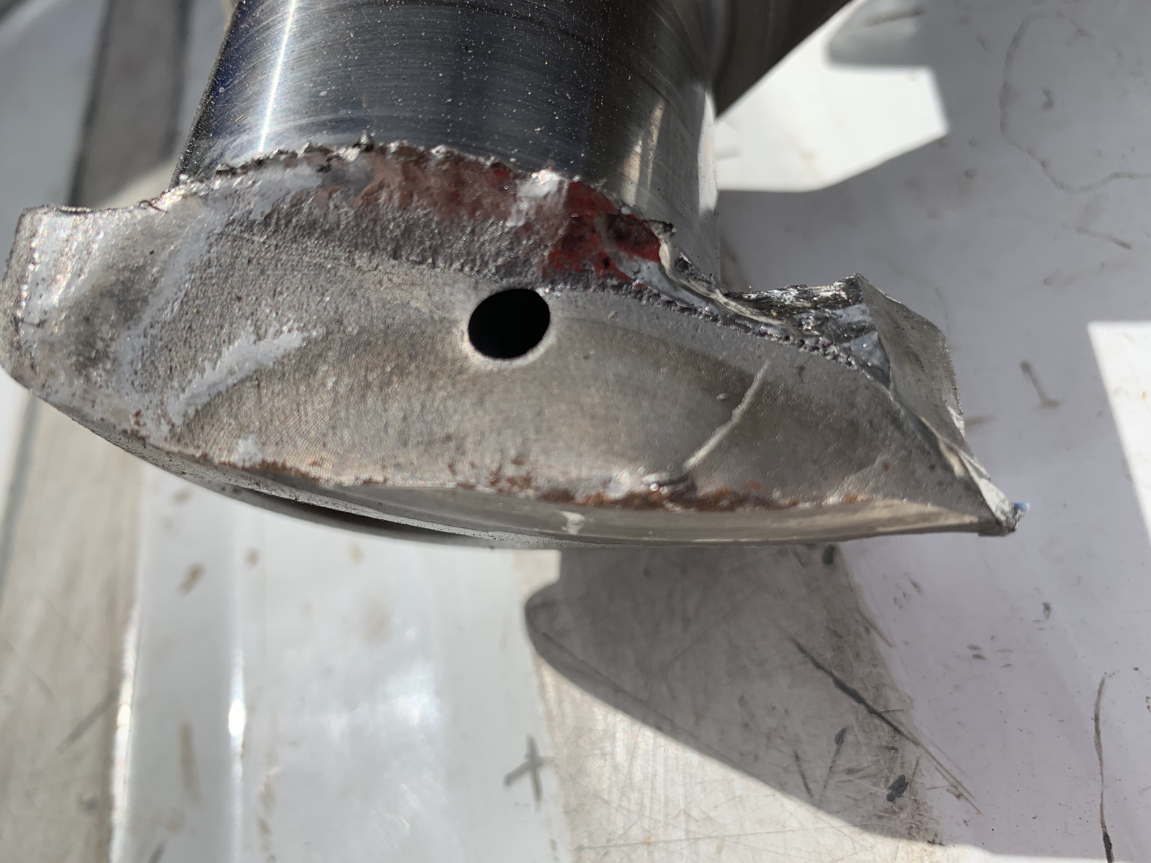
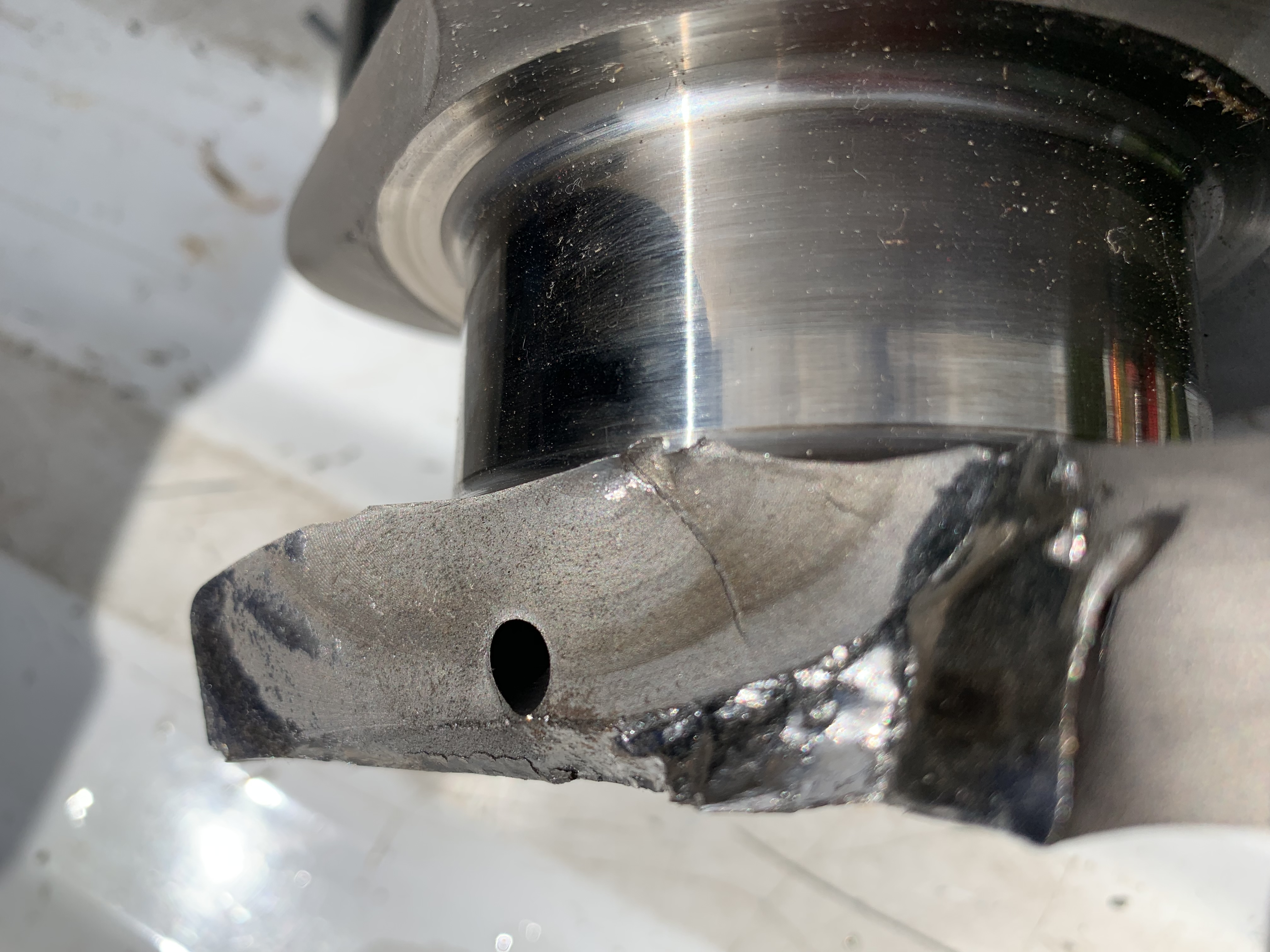
Drag racing provides myriad opportunities to evaluate designs and use virtual methods to predict failures. Crankshafts are one area that is of particular interest as you can't really see inside it and magnafluxing or dye penetrants are dependent on the skill of the technician to execute and interpret properly. This example is more of a post mortem inspection, geometry creation and modal analysis using different boundary conditions to help understand what RPM to stay away from to help the crankshaft live longer.
A little history on this crankshaft is in order to help understand what may have contributed to its failure.
1. First potential contributor may have been when the ring and pinion failed early in a run and allowed the engine to zing unloaded.
2. Second, at 900 feet, a rocker arm broke and oil pressure went to zero. This "blackened" the crank and was polished to restore the bearing surfaces.
3. The NOS hit was increased from 100HP to 300HP. NOS is typically used on this car as a last resort and is only for durations of less than 2 seconds.
4. The crank broke in a big money race immediately after the "button" was hit. The race was won but the damage caused the driver to DNS the next round.
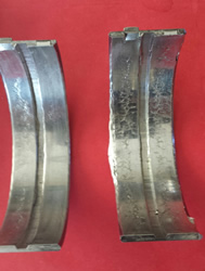
5. Prior to the crank breaking, the #4 main bearing was replaced every 75-125 laps due to the bearing face being overstressed.
The over-stressed face of the King main bearing proved to be an unrecognized symptom of the propagating crack in the main bearing fillet. With this information, the Callies XL Magnum crankshaft was modeled in Solidworks and then analyzed using SIMSOLID and Altair Inspire 2019.3. The modal frequencies were compared to see the agreement between the two solvers as SIMSOLID is a new generation meshless analysis tool.
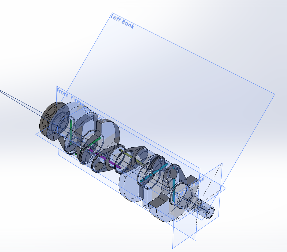
Note that the crank has only 6 counterweights with the #3 main journal between the non-counter weighted webs. The replacement crank is a Bryant unit cut from billet 4340 and is fully counterweighted. It was made for a Top Alcohol engine so it should support 1300HP for considerably longer than the Callies. I'll create the Bryant crank and perform the same modal analysis and see if the modes lower due to the added mass.
Here are the modal analysis results:
Mode Number Inspire SIMSOLID Delta % Engine RPM 1, Bending 195 Hz 189 Hz 3.1% 2835-2925 2, Bending 230 Hz 224 Hz 2.6% 3360-3450 3, Axial 344 Hz 336 Hz 2.3% 5040-5160 4, Axial 466 Hz 458 Hz 1.7% 6870-6990 5, Torsional 478 Hz 473 Hz 1.0% 7110-7170 6, 2nd Order Bending 681 Hz 669 Hz 1.8% 10035-10215 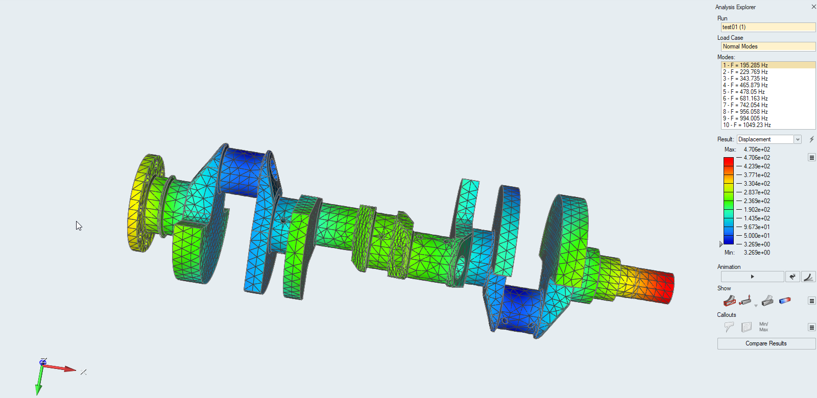
It looks like a bunch of numbers for frequency and somehow they are related to engine RPM but do they give a hint at how the crank behaves? Well, you can see there is an axial bending mode and a torsional mode pretty close to each other from 6870RPM to 7170RPM. Conicidentally, this engine is shifted at 7200RPM, reaches almost 7200RPM at the end of a 1/4 mile and sees close to 1 second of 7000+ RPM during the burnout. So, using a free-free modal analysis we see that two modes may be being excited for more than just a split second during a run. Further analysis will be done that includes the ATI harmonic balancer and a simplified representation of the flywheel/torque convertor. Through experience and using what is called a Holzer table* for estimating torsional modes, the convertor has more inertial mass and will move the failure point closer to the rear of the engine. This coincides with the failure on the "front" side of the #4 main journal. Using this initial information, I can see why a lot of the big block Mopar (hemi) dragster engines run 7500RPM or higher. It makes Modes 4 and 5 just temporary excitations instead of dwelling on them.
*Further analysis using Holzer tables for a Bryant (8 counterweights) and Callies (6 counterweights) Crankshafts including the ATI harmonic balancer and simplified flywheel/torque converter rotational inertias shows the following:
Holzer Table Results
Crankshaft Config 1st Torsional Mode (Hz) Engine RPM Failure Position Bryant 483 7246 Near #4 Main Journal Callies 492 7385 Near #4 Main Journal -
Publications